|
|
125252, Moscow, 12 Aviakonstructor Mikoyan street
Phone: +7 (495) 664-81-71, fax: +7 (495) 664-81-72 |

Pumps Supervisory Control And Data Acquisition System (SCADA)
Application:
The pumps supervisory control and data acquisition system (SCADA) is intended for the following tasks
- Data collection about current operation parameters and equipment status at the water supply system objects;
- Remote control of equipment in operation;
- Recording and backing-up of the system events, process and equipment parameters.
- Borehole water intakes;
- Water tanks;
- Pumping stations of the second and third lift;
- Measuring points;
- Pressure boosting stations.
Advantages:
- Reduction of power consumption;
- Reduction of equipment operation costs;
- Reduction of required service personnel number;
- Reduction of response time for emergency situations;
- Increase of efficiency of the water supply objects;
- Increase of intervals between maintenance;
- Real-time access to actual data of the equipment condition with automatic record of system events and back-up;
- Analysis of accumulated data for optimization of equipment operation.
The system operates in the following modes
- Automatic: all the control panels operate with equipment by preset algorithm; the supervisor performs general control and intervenes in the system’s operation, if necessary, in case of abnormal situations, accidents, etc.
- Manual: the supervisor operates with equipment remotely from his automated workstation.
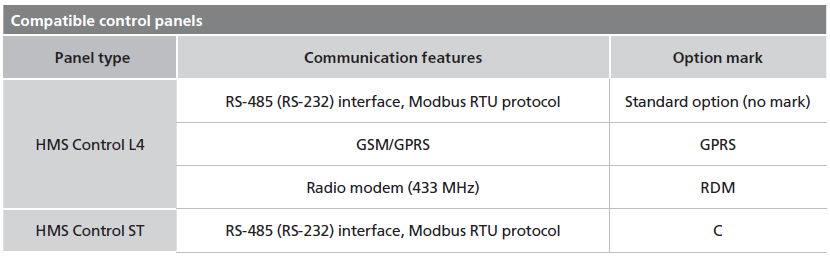
Depending on the objects location and distance between them the following communication ways are applied:
- Wired public or local networks
- GSM / GPRS modem
- 433 MHz radio band
The main elements displayed at the system interface:
- Water supply system objects diagram (can be imposed on the objects’ location map)
- Process scheme of each object
- System events and log of accidents
- Diagrams or tables of the equipment parameters within a period of time
The following data can be displayed on the operator’s automated workstation screen:
- Pressure in pipeline or in the wellhead (for borehole pump)
- Water consumption
- Water levels in tanks
- Temperature of the motor winding or bearings (depending on the pump type)
- Speed of pump shaft (frequency converter is required)
- Electric parameters (e.g. voltage, current)
The operator can perform the following actions from his automated workstation:
- Starting / stopping of the pumping units
- Changing of the pumping units performance (frequency converters are required)
- Control of valves and other processing equipment
- Browsing of the equipment data files, logs and reports for any period (day, month, week, year)
Back to the section
Incorrect information block