Pumps Supervisory Control And Data Acquisition System (SCADA)
Application:
The pumps supervisory control and data acquisition system (SCADA) is intended for the following tasks
Data collection about current operation parameters and equipment status at the water supply system objects;
Remote control of equipment in operation;
Recording and backing-up of the system events, process and equipment parameters.
The system is based on the «HMS Control» series panels
implementing a comprehensive management of the
water supply facilities:
Borehole water intakes;
Water tanks;
Pumping stations of the second and third lift;
Measuring points;
Pressure boosting stations.
The system admits connection to a various supplementary process equipment, valves, etc.
Advantages:
Reduction of power consumption;
Reduction of equipment operation costs;
Reduction of required service personnel number;
Reduction of response time for emergency situations;
Increase of efficiency of the water supply objects;
Increase of intervals between maintenance;
Real-time access to actual data of the equipment condition with automatic record of system events and back-up;
Analysis of accumulated data for optimization of equipment operation.
The system operates in the following modes
Automatic: all the control panels operate
with equipment by preset algorithm;
the supervisor performs general control
and intervenes in the system’s operation,
if necessary, in case of abnormal situations, accidents, etc.
Manual: the supervisor operates with equipment remotely from his automated workstation.
Depending on the objects location and distance between them the following communication ways are applied:
Wired public or local networks
GSM / GPRS modem
433 MHz radio band
The main elements displayed at the system interface:
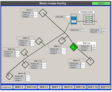
Water supply system objects diagram
(can be imposed on the objects’ location map)
Process scheme of each object
System events and log of accidents
Diagrams or tables of the equipment parameters within a period of time
The following data can be displayed on the operator’s automated workstation screen:
Pressure in pipeline or in the wellhead (for borehole pump)
Water consumption
Water levels in tanks
Temperature of the motor winding or bearings (depending on the pump type)
Speed of pump shaft (frequency converter is required)
Electric parameters (e.g. voltage, current)
The operator can perform the following actions from his automated workstation:
Starting / stopping of the pumping units
Changing of the pumping units performance (frequency converters are required)
Control of valves and other processing equipment
Browsing of the equipment data files, logs and reports for any period (day, month, week, year)